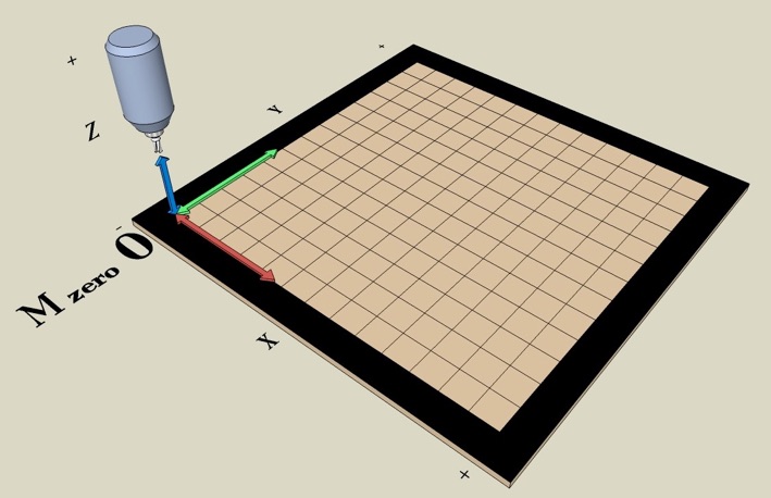
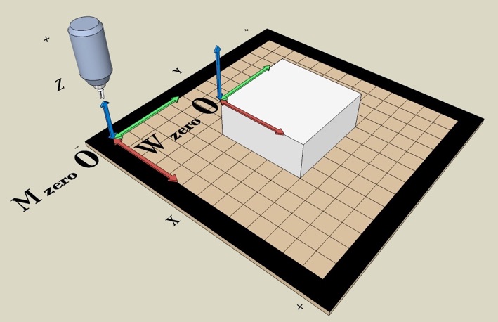
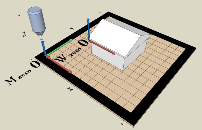
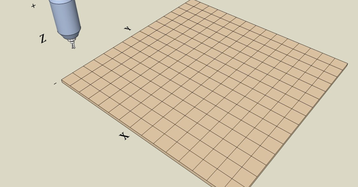
The Working Table

A CNC Milling machine has a table where you fasten the thing you want to mill. The Mill and its Motor can move in any direction, X Left-Right, Y-Back-Forw, and Y Up-Down. In the left corner is a minus sign. All axis are refered to this and are 0 ”Zero”. As an example, If the Mill moves toward the Machines table (Down, it goes negative moving to Zero.


1  X,Y,Z

OTH 2011

M-Zero (Machine Zero)

The Table in whole can not be used as the reference for the M-Zero. Because of the Mechanical movement the X,Y and Z Axis can physical only move without hitting the structure of the Milling Machine. The Motors on a CNC Machine is small, but are VERY strong. A small Motor can easily destroy your Milling Machine in 1/10 of a second if it run out of the M-Zero. The M-Zero is normally setup only once because the table will look the same every time you use the mill.

End Switch

Also called Stop Switch, Limit Switch. The Micro Switch have 3 pin, Common, NO (Normally Open), and NC (Normally Closed). This is the state when not activated. Common is the pin that is either connected to NC or NO. Above is 3 pair of Switches. They are connected so that they are ALWAYS connected in series. Not activated, the output for each Axis to the Computer are Ground (0 Volts) when not activated.

Safety

The Working area the mill can move are like in the box above. To prevent any movement in X,Y and Z outside the box is done by a signal to the computer to STOP all moving. This is simple to do by adding 6 Microswitches, one in each Axes plus and minus end. Mount the Switches so its activated minimum 5 mm BEFORE some part hit the Machine structure. The Switches can be electronic, Proximity etc. but they act the same.

Triggered

In Normal conditions all 3 output to the Computer is 0 Volt. If for example the spindle motor try to pass the Top limit Switch. The Switch Change state and Open so the Output to the Computer goes to 5 Volt and the Computer tells the Motor to stop. Its important to have travel space behind the Limit Switch, it can take some milliseconds to stop. Once stop you have to Reset and move the Spindel motor off the Limit Switch.

W-Zero (Working Zero)

The W-Zero is normally set to your working piece in the same way when you did your CAD drawing. The W-Zero can be set manually with an Edge finder or electrically by ”Tipping” the Workpiece in X,Y and Z direction. Then the Computer will set the W-Zero for the Workpiece. The W-Zero will be different for every new part you are milling, therefore you must set it every time you change Workpiece.

Why 2 Zeros

Its very practical. Think of a House. If you are planing to make a drawing for a new kitchen in the house its difficult to measure all from the corner of the plot. Instead you use a point in the Kitchen as your Zero.  Both M-Zero and W-Zero can be set wherever you want, but use the same direction so you dont confuse yourself.


Happy Milling